¶ Troubleshooting and Solutions for Wobble Issues on the S1 Machine
¶ 1. Vibration Testing and Diagnosis
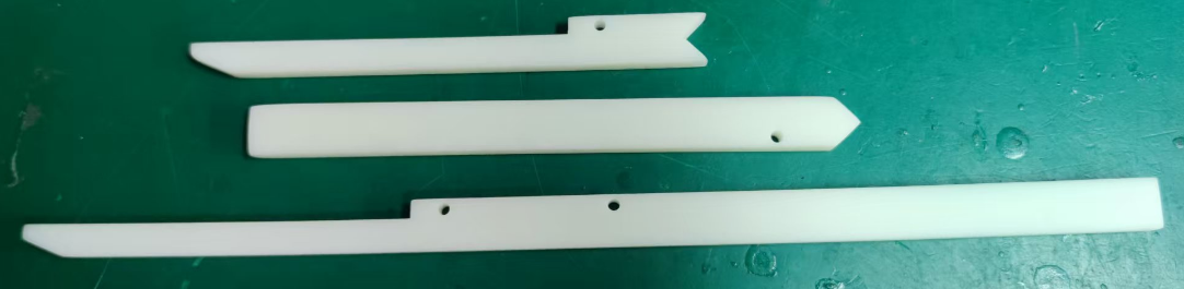
1. Import the test file into LightBurn and engrave it on a wooden board (the length and width of the board must be greater than 400mm)
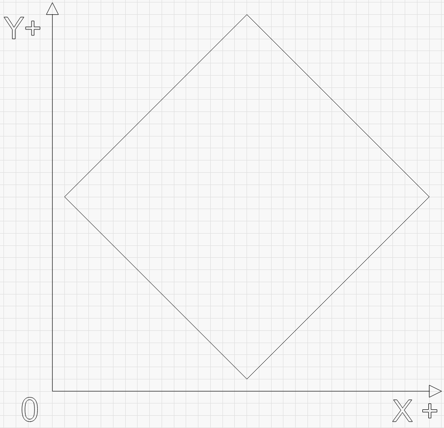
Download LightBurn Test File Below:
/s1manual/s1_machine_jitter_test_file.lbrn2
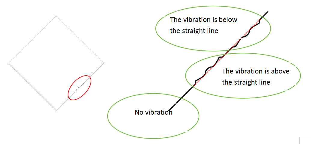
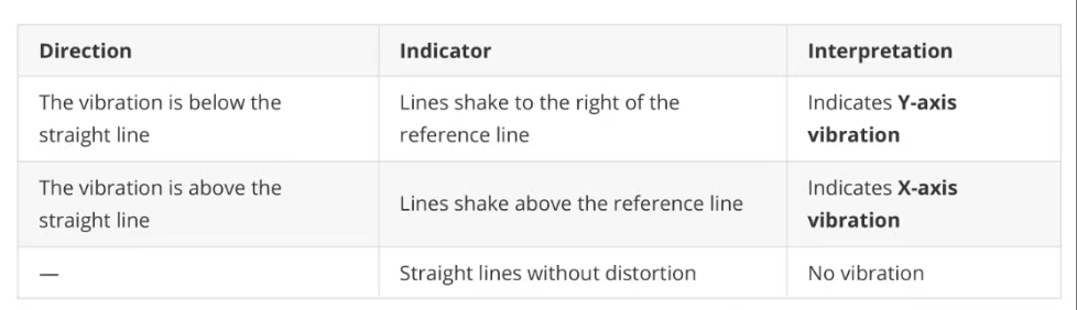
2. Use the engraved lines to determine which axis is causing the vibration on the S1 machine.
¶ 2. Causes and Solutions
¶ 2.1 Y-axis Vibration Causes and Solutions:
¶ Cause 1: The drag chain rubs against itself at high speeds, causing the laser module to shake.
Solution: install a 3D-printed drag chain support bracket on the Y-axis. (https://wiki.tyvok.com/en/Drag_Chain)
¶ Cause 2:
The back plate or hand screws that fix the laser head are not tightened; there is no jitter when the laser head is running at low power, but when the laser head is running at full power, the internal fan rotates at high speed and resonates, causing jitter during the engraving process.
Solution: Check whether the back plate and hand screws that fix the laser head are tightened.
¶ 2.2 X-Axis Wobble
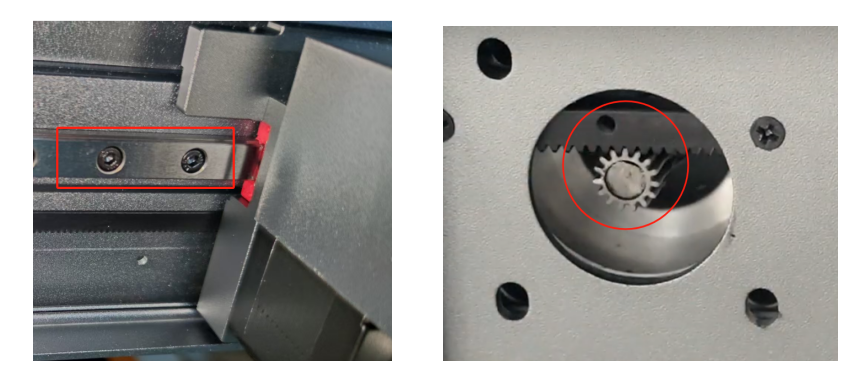
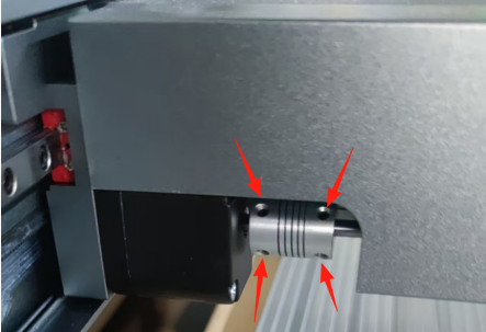
¶ Cause 1: The set screws on the couplers have come loose, causing the gears on both sides to fall out of sync,resulting in vibration.
Solution: Check whether the set screws on the couplers are tightened
¶ Cause 2: Too many steel balls (more than 3) were lost during machine assembly, causing intense vibration andloud noise during operation.
Solution: Contact customer service to replace the Y-axis slide block.
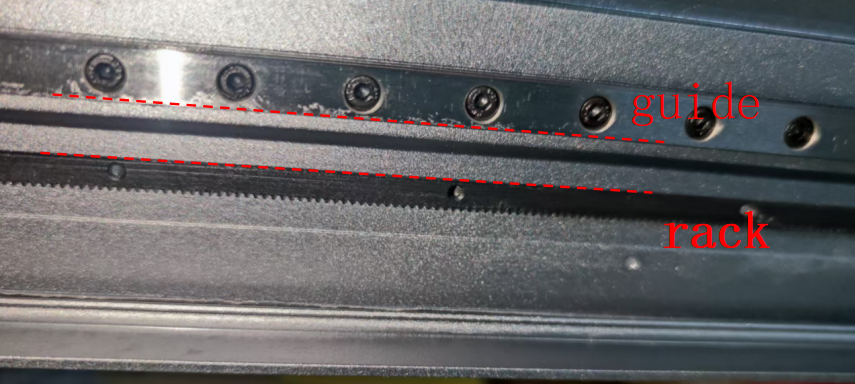
¶ Cause 3: Poor parallelism between the guide rail guiding surface and the rack reference surface.
Solution:
- Adjust the frame joints to align them.
- Fine-tune the guide rails to keep good parallelism with the rack.
- Adjust the gear–rack clearance to ensure proper meshing.
¶ Adjust the Frame Joints to Align Them
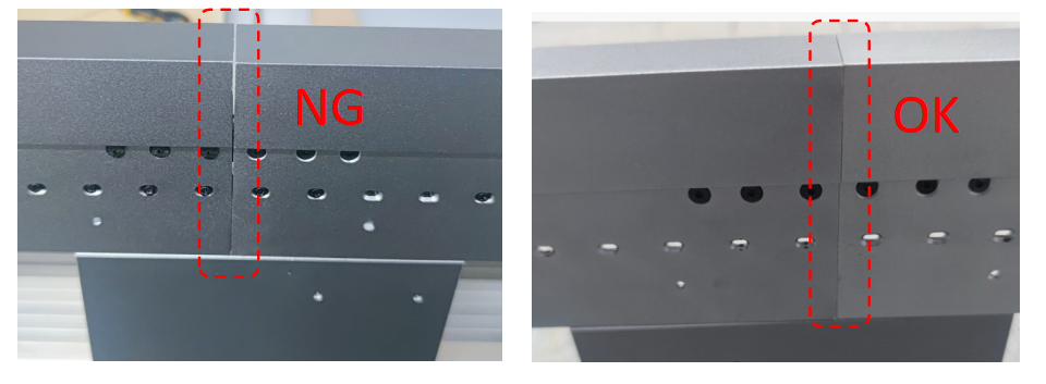
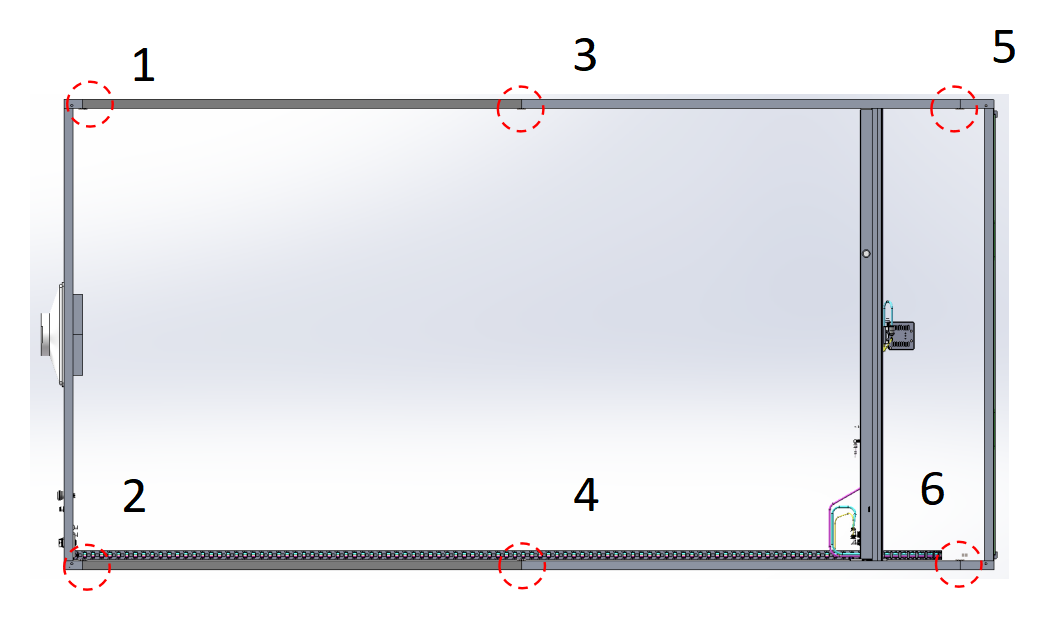
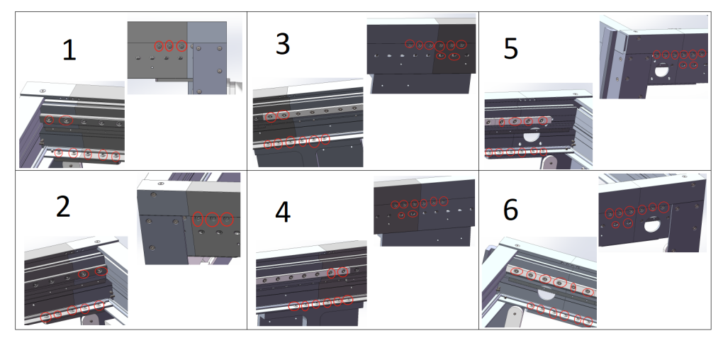
The screws corresponding to each position are marked with a red circle.
Correction Method:
- Loosen the screws at the required correction positions (turn counterclockwise three turns, no need to remove).
- After aligning the seams, retighten the screws in sequence according to the diagram.
Illustrations:
- OK / NG seam examples.
- Locations 1–6 corresponding to frame screws.
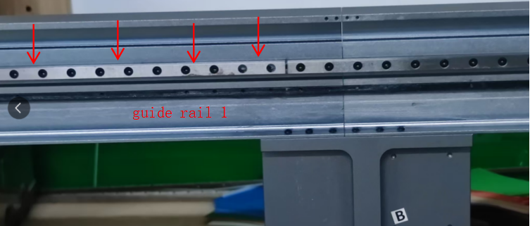
¶ Fine-tune the Guide Rails to Maintain Parallelism with the Rack
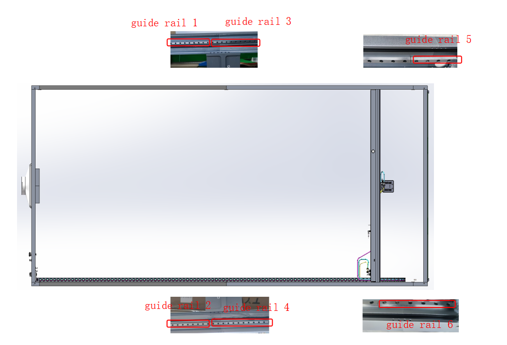
Push the Y-axis beam to the right, loosen all fixing screws of guide rail 1 and guide rail 2 (turn counterclockwise three turns, no need to remove).
Press the guide rail downward from the top (arrow direction), then tighten all fixing screws (each guide rail has 65 pcs screws).
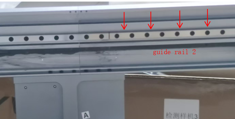
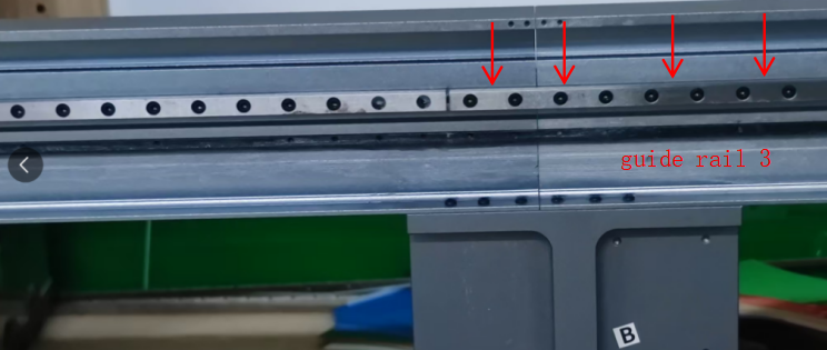
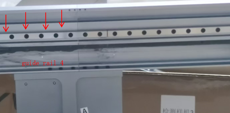
Push the Y-axis beam to the left, loosen all fixing screws of guide rail 3 and guide rail 4.
Press downward from the top (arrow direction), then tighten all fixing screws (65 pcs per guide rail).
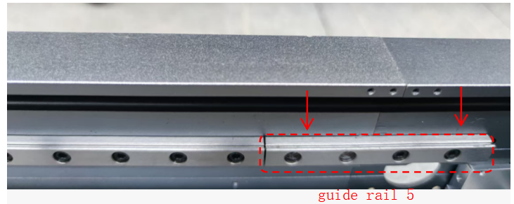
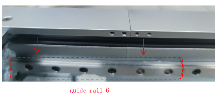
Push the Y-axis beam to the left, loosen all fixing screws of guide rail 5 and guide rail 6.
Press downward from the top (arrow direction), then tighten all fixing screws.
¶ Adjust the Gear–Rack Clearance
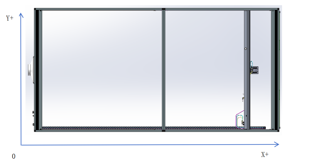
Remove the laser head and back plate, then move the Y-axis beam to the far-right “maintenance position.”
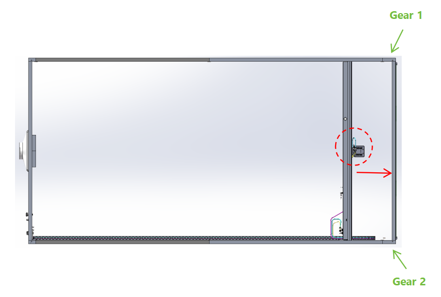
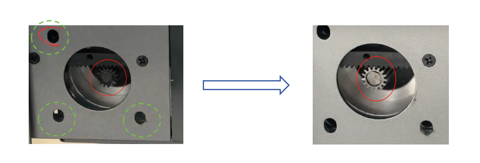
- Gear 1 Adjustment: Loosen the three fixing screws (turn counterclockwise three turns, no need to remove).
Move the gear upward to achieve proper meshing with the rack, then tighten the three screws.
Video link: 4:40~6:40, please check the video at this period.
- Gear 2 Adjustment: Refer to the existing tutorial.
Wiki link: http://wiki.tyvok.com/en/tyvok-s1
¶ 3. Other Consideration
1. Ensure the platform where the machine is placed is level and stable. An uneven or shaky surface can alsocause vibrations during operation.
2. The drive system of the machine should be lubricated every three months to extend its service life(lithium grease is highly recommended).